Pages

Sunday, January 9, 2011

Tele-Graffiti


Tele-graffiti is a technology that allows two or more users to communicate remotely via hand-drawn sketches. What one person writes at one site is captured by a video camera, transmitted to the other site and displayed there using an LCD projector.
The system was developed at Robotics Institute of Carnegie Mellon university, Pittsburg. The system comprises of a digital camera, a high resolution LCD projector to project the received image, a mirror to reflect the projected image onto the paper, fixture to hold these devices in position and a writing pad to fix the sheet of paper on the top of the table at every station.
The user can write on a regular piece of paper with a pen at his desk. The sketch or writing on the paper is captured by the camera and transmits the digitized image to the receiving end through a data link.
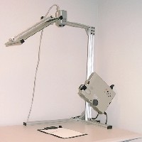
The image can be transmitted over the internet or local area network. The software architecture of system runs on Linux  and has four threads the drawing thread, the paper tracking thread, sending thread and receiving thread.
Tele-graffiti has various applications. It can play an important role in remote education and remote designing.
It can also serve as a substitute for internet chat. The advantage of the system is that non-computer people can use it. .

Power over Ethernet (PoE)


Power over Ethernet (PoE) is a revolutionarytechnology that extends the already ultra-broad functionality of Ethernet by supplying reliable DC power over the same twisted-pair cable that currently carries Ethernet data.
PoE, modeled after the technology used by the telecommunications industry to supply reliable power to telephones, enables lifeline quality power for IP telephones (VoIP) as well as many other low power Ethernet network devices like wireless access points (WAP) and security cameras.
When locating access points, system designers often use the availability of AC (alternating current) electrical outlets to base decisions on where to install access points. In some cases, companies only locate access points near AC outlets and within reach of a typical six foot electrical cord.
Or, they'll look for a convenient location to install new outlets at points where it's suitable to run conduit and mount outlet boxes. All of these situations limit the location of access points and can incur significant costs if new outlets must be installed.
Power-over-Ethernet (PoE) solves these problems. A PoE solution only requires technicians to run one Ethernet cable to the access point for supplying both power and data.
With PoE, power-sourcing equipment detects the presence of an appropriate "powered device" (e.g., an access point or Ethernet hub) and injects applicable current into the data cable.
An access point can operate solely from the power it receives through the data cable.

Subversion


Engineering revision control developed from formalized processes based on tracking revisions of early blueprints or bluelines. Implicit in this control was the option to be able to return to any earlier state of the design, for cases in which an engineering dead-end was reached in iterating any particular engineering design.
Likewise, in computer software engineering, revision control is any practice which tracks and provides controls over changes to source code. Software developers sometimes use revision control software to maintain documentation and configuration files as well as source code.
In theory, revision control can be applied to any type of information record. In practice, however, the more sophisticated techniques and tools for revision control have rarely been used outside software development circles (though they could actually be of benefit in many other areas).
However, they are beginning to be used for the electronic tracking of changes to CAD files, supplanting the "manual" electronic implementation of traditional revision control.
As software is developed and deployed, it is extremely common for multiple versions of the same software to be deployed in different sites, and for the software's developers to be working privately on updates. Bugs and other issues with software are often only present in certain
versions (because of the fixing of some problems and the introduction of others as the program evolves).

Therefore, for the purposes of locating and fixing bugs, it is vitally important for the debugger to be able to retrieve and run different versions of the software to determine in which version(s) the problem occurs.
It may also be necessary to develop two versions of the software concurrently (for instance, where one version has bugs fixed, but no new features, while the other version is where new features are worked on).
At the simplest level, developers can simply retain multiple copies of the different versions of the program, and number them appropriately. This simple approach has been used on many large software projects.
Whilst this method can work, it is inefficient (as many near-identical copies of the program will be kept around), requires a lot of self-discipline on the part of developers, and often leads to mistakes.
Consequently, systems to automate some or all of the revision control process have been developed.

Fluid Focus Lens


The camera phone is one of the hottest-selling items in all of consumer electronics. The little gadgets have become so ubiquitous that hardly anyone finds it odd anymore to see tourists squinting with one eye while pointing their cell phones at a Buddhist temple, a Greek statue, or a New York City skyscraper.
It's easy to see why analysts expect that camera phones will outsell conventional digital cameras and traditional film cameras combined.

But as anyone who has ever seen them can attest, the images that come out of camera phones leave plenty to be desired. Part of the problem is their CMOS imaging chips, which typically have a sensor array of only about one mega pixel—a half or less of the number in a low-end digital camera. 

When they are, however, the only thing we may see more clearly is the other weakness of these cameras: their tiny, fixed-focus lenses, which have poor light-gathering and resolving power.

Here is a solution. It's modeled on the human eye, with its remarkable optical capabilities.  It is called  the FluidFocus lens. Like the lens of the eye, this lens, which we built at Philips Research Laboratories, in Eindhoven, the Netherlands, varies its focus by changing shape rather than by changing the relative positions of multiple lenses, as high-quality camera lenses do.

The tests of a prototype FluidFocus lens showed that it can be made nearly as small as a fixed-focus lens. Fixed-focus lenses use a small aperture and short focal length to keep most things in focus, but at the sacrifice of light-gathering power and therefore of picture quality.

At the same time, the prototype lens delivered sharpness that is easily on a par with that of variable-focus lenses. In fact, the optical quality of a liquid lens combined with a good imaging chip could soon give cell phone snapshots quality that rivals images from conventional- and much bulkier- digital cameras.

Silicon Photonics


Silicon photonics can be defined as the utilization of silicon-based materials for the generation (electrical-to-optical conversion), guidance, control, and detection (optical-to-electrical conversion) of light to communicate information over distance.
The most advanced extension of this concept is to have a comprehensive set of optical and electronic functions available to the designer as monolithically integrated building blocks upon a single silicon substrate.

Within the range of fibre optic telecommunication wavelength (1.3 µm to 1.6 µm), silicon is nearly transparent and generally does not interact with the light, making it an exceptional medium for guiding optical data streams between active components.

But no practical modification to silicon has yet been conceived which gives efficient generation of light. Thus it required the light source as an external component which was a drawback.

There are two parallel approaches being pursued for achieving opto-electronic integration in silicon. The first is to look for specific cases where close integration of an optical component and an electronic circuit can improve overall system performance.

One such case would be to integrate a SiGe photodetector with a Complementary Metal-Oxide-Semiconductor (CMOS) transimpedance amplifier. The second is to achieve a high level of photonic integration with the goal of maximizing the level of optical functionality and optical performance.
This is possible by increasing light emitting efficiency if silicon. The paper basically deals with this aspect.

Embedded DRAM


his paper examines some aspects of the architecture of embedded DRAM (dynamic random access memory), its applications and its advantages over other conventional memory types.
Embedded DRAM (eDRAM) – the concept of merging DRAM with logic on a single device – has become increasingly popular, thanks to the growth of existing and emerging high bandwidth applications such as graphics processing, backbone and access router data communications systems and base stations for mobile phones.
A common requirement of all these designs is that they have to process very large amounts of data at very high speeds. Because of this, a fundamental design requirement is the ability to provide high performance, high speed memory access.
One way of achieving this is to use system-on-chip (SoC) solutions that incorporate embedded DRAM, allowing wide on chip buses to connect logic to DRAM on the same die, rather than to external memory.
Furthermore, integration of DRAM directly into an LSI device has the added benefits of minimising system power consumption, saving board space, reducing component count and, thanks to the elimination of external buses, reducing the effects of EMI.
eDRAM is used in areas that require high memory bandwidth like in graphics accelerators and media-oriented vector processors like the Vector IRAM (VIRAM)..

Saturday, January 8, 2011

Terahertz Waves And Applications


Imaging technology has a rich history that began thousands of years ago. The reflection from a pool of still water or a shiny metal surface was arguably the first imaging method routinely used by mankind. With the advent of lenses, many other novel forms of optical imaging emerged, including telescopes and microscopes.
Using a lens, a pinhole camera, and a sensitized pewter plate, Niépce was the first person to permanently record an image. Optical photography and other forms of optical imaging have since become commonplace.
Of course, imaging has not been constrained to optical frequencies. In 1895 Roentgen discovered X-rays. As with X-rays, whenever a portion of the electromagnetic (EM) spectrum became practically usable, it wasn’t long before it was adapted to an imaging configuration.
Therefore, it is not surprising that many types of imaging systems exist today and utilize the radio, microwave, infrared (IR), visible, ultraviolet, X-ray, and gamma ray portions of the EM spectrum.
Pressure waves have also been adapted to imaging and are manifest in the various forms of ultrasonic and   sonographic imaging systems.
     Terahertz (THz) radiation (0.1 THz to 10 THz, 1 THz = 1012 Hz) lies between the                infrared (night vision cameras) and microwave (operating range of mobile phones) region        of the electromagnetic spectrum.
What makes these waves so fascinating to scientists is their ability to penetrate materials that are usually opaque to both visible and infrared radiation. For example, terahertz waves can pass through fog, fabrics, plastic, wood, ceramics and even a few centimeters of brick - although a metal object or a thin layer of water can block them.
The way in which terahertz waves interact with living matter has potential for highlighting the early signs of tooth decay and skin or breast cancer, or understanding cell dynamics.

VT Architecture


Parallelism and locality are  the  key application characteristics  exploited  by computer architects to make productive use of increasing transistor counts while coping with wire delay and power dissipation. Conventional sequential ISAs provide minimal  support  for encoding parallelism or locality, so high-performance implementations are forced to devote considerable area and power to on-chip structures that extract parallelism or that support arbitrary global communication. The large area and power overheads are justified by the demand for even small improvements in  performance  on legacy codes  for popular ISAs. Many important applications have abundant parallelism,  however, with dependencies and communication patterns that can be statically determined. ISAs that  expose  more  parallelism reduce the need for area and power intensive structures to extract  dependencies dynamically. Similarly,  ISAs that  allow  locality to  be expressed reduce the need for long range communication and  complex  Interconnect.

                                                 The challenge  is  to develop an efficient encoding  of  an  application’s parallel  dependency graph and to reduce the area and power consumption of the micro architecture that will execute this  dependency  graph. All  these challenges  are  met by  unifying the vector and  multithreaded  execution  models  with  the vector-thread (VT) architectural paradigm. VT  allows large amounts of  structured parallelism  to  be compactly encoded in a form that allows a simple micro architecture to attain high performance  at  low power  by  avoiding  complex  control and   datapath  structures   and by reducing activity on long wires. 
The VT  programmer’s  model  extends  a conventional scalar control processor with an array of slave virtual processors (VPs). VPs execute strings of RISC-like  instructions  packaged  into  atomic  instruction  blocks (AIBs). To execute  data-parallel code,  the control processor  broadcasts AIBs  to  all  the slave VPs. To execute thread parallel code,  each VP  directs  its  own  control  flow by fetching its own AIBs. Implementations of the VT architecture can also exploit instruction-level parallelism within AIBs. In this way, the VT architecture supports a
modeless  intermingling of all forms of application parallelism. This  flexibility  provides new  ways to  parallelize  codes  that  are  difficult  to vectorize  or  that  incur   excessive synchronization costs when threaded.  Instruction locality is  improved  by  allowing common  code  to  be  factored  out and  executed  only once  on  the  control  processor,  and  by  executing  the  same  AIB  multiple  times  on  each  VP  in  turn.   Data  locality  is improved as most operand communication is isolated to within an individual VP.

SCALE, a prototype processor, is an instantiation of the vector-thread architecture designed for low-power and high-performance embedded systems. As transistors have become cheaper and faster, embedded applications have evolved from simple control functions to cellphones that run multitasking networked operating systems with real time video, three-dimensional graphics, and dynamic compilation of garbage collected languages. Many other embedded applications require sophisticated high-performance information processing, including streaming media devices, network routers, and wireless base stations. Benchmarks taken from these embedded domains can be mapped efficiently to the SCALE vectorthread architecture. In many cases, the codes exploit multiple types of parallelism simultaneously for greater efficiency

Zigbee - zapping away wired worries


In recent years there has been rapid development in the wireless sector due to demand for wire free connectivity. Most of the development was focused on high data rate applications like file transfer etc with new standards like Bluetooth emerging.
During this time applications that required lower data rates but had some other special requirements were neglected in the sense that no open standard was available.
Either these applications we abandoned in the wireless arena or implemented using proprietary standards hurting the interoperability of the system.
ZigBee is a wireless standard that caters to this particular sector. Potential applications of ZigBee include Home Automation, Wireless Sensor Networks, Patient monitors etc. The key features of these applications and hence aims of ZigBee are
  1. Low Cost
  2. Low Power for increased battery life
  3. Low Range
  4. Low Complexity
  5. Low Data Rates
  6. Co-Existence with other long range Wireless Networks
The ZigBee standard is maintained by ZigBee Alliance is a spin off of the HomeRF group, an unsuccessful home automation related consortium.
It is built upon the IEEE 802.15.4 protocol which is intended for LR-WPAN (Low Rate - Wireless Personal Area Network).
In this seminar a general overview of ZigBee is followed by an analysis of how ZigBee and underlying 802.15.4 provide the aims mentioned. Also a brief comparisons with other solutions will be done.

Radiation Hardened Chips


Space is a hostile environment. No atmosphere, extreme variations in temperature and almost no energy sources, where even the slightest of mistakes can lead to a disaster. The vast emptiness of space is filled with radiation, mostly from the sun.
A normal computer unless given proper shielding will not be able to work properly. Thus special types of chips- rad hard chips are used.
               
                 Radiation hardened chips are made by two methods: -
  • Radiation hardening by process (RHBP)
  • Radiation hardening by design (RHBD)
The latter method is much more cost effective and has a great potential for the future. . It has been demonstrated that RHBD techniques can provide immunity from total-dose and single-event effects in commercially produced circuits.
Commercially produced RHBD memories, microprocessors, and application-specific integrated circuits are now being used in defense&space industry.
Rad hard chips have a great scope in military application and protecting critical data (both industrial &domestic) from the vagaries of man and nature.


  Current trends throughout military and space sectors favor the insertion of commercial off-the-shelf (COTS) technologies for satellite applications.
However, there are also unique concerns for assuring reliable performance in the presence of ionizing particle environments which present concerns in all orbits of interest. This seminar will detail these concerns from two important perspectives including premature device failure from total ionizing dose and also single particle effects which can cause both permanent failure and soft errors.

Terahertz Transistor


MOS transistor is the building block of integrated circuits, and is the engine that powers them. Today’s most complex ICs, such as microprocessors, graphics, and DSP chips, pack more than 100 million MOS transistors on a single chip. Integration of one billion transistors into a single chip will become a reality before 2010.                    
                    The semiconductor industry faces an environment that includes increasing chip complexity, continued cost pressures, increasing environmental regulations, and growing concern about energy consumption. New materials and technologies are needed to support the continuation of Moore's law.                                         
                        Moore's Law was first postulated in 1965 and it has driven the research, development, and investments in the semiconductor industry for more than three decades. The observation that the number of transistors per integrated circuit doubles every eighteen to twenty four months is well known to industry analysts and many of the general public.

However, what is sometimes overlooked is that fact that Moore's law is an economic paradigm: that is, the cost of a transistor on an integrated circuit needs to be reduced by one half every two years.
This type of cost reduction cannot be sustained for an    extended   period by    straightforward    continuous     improvement    of existing technologies.
The semiconductor industry will face a number of challenges during this decade where new materials and new technologies will need to be introduced to support the continuation of Moore's Law.

FinFET Technology


The introduction of FinFET Technology has opened new chapters in Nano-technology.  Simulations show that FinFET structure should be scalable down to 10 nm.  Formation of ultra thin fin enables suppressed short channel effects.
  It is an attractive successor to the single gate MOSFET by virtue of its superior electrostatic properties and comparative ease of manufacturability.                
Since the fabrication of MOSFET, the minimum channel length has been shrinking continuously. The motivation behind this decrease has been an increasing interest in high speed devices and in very large scale integrated circuits.
The sustained scaling of conventional bulk device requires innovations to circumvent the barriers of fundamental physics constraining the conventional MOSFET device structure. The limits most often cited are control of the density and location of dopants providing high I on /I off ratio and finite subthreshold slope and quantum-mechanical tunneling of carriers through thin gate from drain to source and from drain to body.
Double balanced Gilbert mixer with RF & LO input baluns in FinFET technology. © NANO-RFThe channel depletion width must scale with the channel length to contain the off-state leakage I off. This leads to high doping concentration, which degrade the carrier mobility and causes junction edge leakage due to tunneling. Furthermore, the dopant profile control, in terms of depth and steepness, becomes much more difficult.
The gate oxide thickness tox must also scale with the channel length to maintain gate control, proper threshold voltage VT and performance. The thinning of the gate dielectric results in gate tunneling leakage, degrading the circuit performance, power and noise margin.

Magnetic Amplifiers


A magnetic amplifier is a device which controls the power delivered from an a.c. source by employing a controllable non linear reactive elements or circuit generally interposed in series with the load. The power required to control the reactive element or circuit is made for less than the amount of power controlled; and hence power amplification is achieved. The non-linear reactive element is a saturable reactor. When used in a combination with a set of high-grade rectifiers, it exhibits power amplification properties in the sense that small changes in control power result in considerable changes in output power. The basic component of a magnetic amplifier, as mentioned above, is the saturable reactor. It consists of a laminated core of some magnetic material. The hysteresis loop of the reactor core is a narrow and steep one. A schematic diagram of a simple saturable core reactor with control winding and a.c. winding wound on two limbs. Thecontrol winding having a number of turns, Na.c. is fed with d.c. supply. By varying the control current, it is possible to largely vary the degree of saturation of the core. The other winding, called the a.c. winding or gate winding having a number of turns, Na.c. is fed from an a.c. source, the load being connected in series with it.
The property of the reactor which makes it behave as a power amplifier is its ability to change the degree of saturation of the core when the control winding mmf (magneto motive force i.e., ampere turns), established by d.c. excitation, is changed. The a.c. power supply will have high impedance if the core is unsaturated and the varying values of lower impedances as the core is increasingly saturated. When the core is completely saturated, the impedance of the a.c. winding becomes negligibly small and the full a.c. voltage appears across the load. Small values of current through the control winding, which has a large number of turns, will determine the degree of saturation of the core and hence change the impedance of the output circuit and control the flow of current through the load. 

By making the ratio of control winding turns to the a.c. winding turns large, an extremely high value of output current can be controlled by a very small amount of control current, The saturable core reactor circuit shown in Fig. has certain serious disadvantages. The core gets partially desaturated in the half-cycle in which the a.c. winding mmf opposes the control winding mmf. This difficulty is overcome by employing a rectifier in the output circuit as shown in Fig. Here the desaturating (damagnetising) effect by the half-cycle of the output current is blocked by the rectifier. On the other hand, the output and control winding mmfs aid each other to effect saturation in the half-cycle in which current passes through the load, thus making the reactor a self-saturating magnetic amplifier.
 Another difficulty that is experienced is that a high voltage is induced in the control winding due to transformer action. In order that this voltage is unable to send current to the d.c. circuit a high inductance should be connected in series with the control winding. This, however, slows down the response of the control system and hence the overall system. The saturable core is generally made of a saturable ferromagnetic material. For magnetic amplifiers of lower ratings usual transformer type construction using silicon steel (3 to 3.5 per cent Si) is used. Use of high quality nickel-iron alloy materials, however , makes possible much higher performance amplifiers of smaller size and weight. In order to realize the advantages of these materials, use is made of toroidal core configuration.

Illumination With Solid State Lighting


A Light emitting diodes (LEDs) have gained broad recognition as the ubiquitous little lights that tell us that our monitors are on, the phone is off the hook or the oven is hot semiconductor.
The basic principle behind the emission of light is that: When charge carrier pairs recombine in a semiconductor with an appropriate energy band-gap generates light. In a forward biased diode, little recombination occurs in the depletion layer. Most occurs in a few microns of either P- region or N –region, depending on which one is lightly doped.
LEDs produce narrow band radiations, with wave length determined by energy band of the semiconductor. Solid state electronics have replaced their vacuum tube predecessors for almost five decades. However in the next decade they will be brighter, more efficient and inexpensive enough to replace conventional lighting sources (i.e. incandescent bulbs, fluorescent tubes).
Recent development in AlGaP and AlInGaP blue and green semiconductor growth technology have enabled applications where several single to several millions of these indicator LEDs can be packed together to be used in full color signs, automotive tail lambs, traffic lights etc. still the preponderance of applications require that the viewer has to look directly into the LED. This is not “SOLID STATE LIGHTING”
              Artificial lighting sources share three common characteristics:
       -They are rarely viewed directly: light from sources are viewed as reflection off  the illuminated object.
      - The unit of measure is kilo lumen or higher not mille lumen or lumen as it is incase of LEDs
      -Lighting sources are pre dominantly white with CIE color coordinates, producing excellent color rendering
         Today there is no such commercially using “SOLID STATE LAMP” However high power LED sources are being developed, which will evolve into lighting 

sources

Electrical Impedance Tomography Or EIT


To begin with, the word tomography can be explained with reference to ‘tomo’ and
‘graphy’; ‘tomo’ originates from the Greek word ‘tomos’ which means section or slice,
and ‘graphy’ refers to representation. Hence tomography refers to any method which 

involves reconstruction of the internal structural information within an object mathematically from a series of projections.
The projection here is the visual information probed using an emanation which are physical processes involved. These include physical processes such as radiation, wave motion, static field, electric current etc. which are used to study an object from outside.Medical tomography primarily uses X-ray absorption, magnetic resonance, positron emission, and sound waves (ultrasound) as the emanation.
 Nonmedical area of application and research use ultrasound and many different frequencies of electromagnetic spectrum such as microwaves, gamma rays etc. for probing the visual information.
Besides photons, tomography is regularly performed using electrons and neutrons. In addition to absorption of the particles or radiation, tomography can be based on the scattering or emission of radiation or even using electric current as well.When electric current is consecutively fed through different available electrode pairs and the corresponding voltage, measured consecutively  by all remaining electrode pairs, it is possible to create an image of the impedance of different regions of the volume conductor by using certain reconstruction algorithms. This imaging method is called impedance imaging.
admittance (admittivity) or specific impedance (impedivity) of tissue rather than the conductivity; hence, electric impedance tomography. Thus, EIT is an imaging method which maybe used to complement X-ray tomography (computer tomography, CT), ultrasound imaging, positron emission tomography (PET), and others.Because the image is usually constructed in two dimensions from a slice of the volume conductor, the method is also called impedance tomography and ECCT (electric current computed tomography), or simply, electrical impedance tomography or EIT.Electrical Impedance Tomography (EIT) is an imaging technology that applies time-varying currents to the surface of a body and records the resulting voltages in order to reconstruct and display the electrical conductivity and permittivity in the interior of the body. This technique exploits the electrical properties of tissues such as resistance and capacitance. It aims at exploiting the differences in the passive electrical properties of tissues in order to generate a tomographic image.Human tissue is not simply conductive. There is evidence that many tissues also demonstrate a capacitive component of current flow, and therefore, it is appropriate to speak of the specific impedance (impedivity) of tissue rather than the conductivity; hence, electric impedance tomography. Thus, EIT is an imaging method which maybe used to complement X-ray tomography (computer tomography, CT), ultrasound imaging, positron emission tomography (PET), and others.

Immersion Lithography


The growth of the semiconductor industry is driven by Moore’s law: “The complexity for minimum component cost has increased at a rate of roughly a factor of two per year”. Notice that Moore observed that not only was the number of components doubling yearly, but was doing so at minimum cost.
One of the main factors driving the improvements in complexity and cost of ICs is improvements in optical lithography and the resulting ability to print ever smaller features.
Recently optical lithography, the backbone of the industry for 45 years has been pushing up against a number of physical barriers that have led to massive investments in development of alternate techniques such as Scalpel, Extreme Ultraviolet and others.
                     Since the mid eighties, the demise of optical lithography has been predicted as being only a few years away, but each time optical lithography approaches a limit, some new technique pushes out the useful life of the technology.
The recent interest in immersion lithography offers the potential for optical lithography to be given a reprieve to beyond the end of the decade.

Low Power Wireless Sensor Network


Wireless distributed microsensor systems will enable fault tolerant monitoring and control of a variety of applications. Due to the large number of microsensor nodes that may be deployed and the long required system lifetimes, replacing the battery is not an option.
Sensor systems must utilize the minimal
possible energy while operating over a wide range of operating scenarios. This paper presents an overview of the key technologies required for low-energy distributed microsensors.

These include
  • power aware computation/communication component technology
  • low-energy signaling and networking
  • system partitioning considering computation
  • communication trade-offs
  • a power aware software infrastructure.

Tri-Gate Transistor


Transistors are the microscopic, silicon-based switches that process the ones and zeros of the digital worlds and are the fundamental building block of all semiconductor chips. With traditional planar transistors, electronic signals travel as if on a flat, one-way road. This approach has served the semiconductor industry well since the 1960s. But, as transistors shrink to less than 30 nanometers (billionths of a meter), the increase in current leakage means that transistors require increasingly more power to function correctly, which generates unacceptable levels of heat.

Intel's tri-gate transistor employs a novel 3-D structure, like a raised, flat plateau with vertical sides, which allows electronic signals to be sent along the top of the transistor and along both vertical sidewalls as well. This effectively triples the area available for electrical signals to travel, like turning a one-lane road into a three-lane highway, but without taking up more space. Besides operating more efficiently at nanometer-sized geometries, the tri-gate transistor runs faster, delivering 20 percent more drive current than a planar design of comparable gate size.


The tri-gate structure is a promising approach for extending the TeraHertz transistor architecture Intel announced in December 2001. The tri-gate is built on an ultra-thin layer of fully depleted silicon for reduced current leakage. This allows the transistor to turn on and off faster, while dramatically reducing power consumption. It also incorporates a raised source and drain structure for low resistance, which allows the transistor to be driven with less power. The design is also compatible with the future introduction of a high K gate dielectric for even lower leakage.
Intel researchers have developed "tri-gate" transistor design. This is one of the major breakthroughs in the VLSI technology. The transistor is aimed at bringing down the transistor size in accordance with the Moore’s Law. The various problems transistors with very small size face have to be overcome. A reduction in power dissipation is another aim. This is to develop low power micro processors and flash memories.

Tri-gate transistors show excellent DIBL, high sub threshold slope, high drive and much better short channel performance compared to CMOS bulk transistor. The drive current is almost increased by 30%. The thickness requirement of the Si layer is also relaxed by about 2-3 times that of a CMOS bulk transistor.
Tri- gate transistors are expected to replace the nanometer transistors in the Intel microprocessors by 2010. 60 nm tri-gate transistors are already fabricated and 40 nm tri-gate transistors are under fabrication. Tri-gate transistor is going to play an important role in decreasing the power requirements of the future processors. It will also help to increase the battery life of the mobile devices.

DSP Enhanced FPGA


Rapid advances in silicon technology and high demand of multimedia applications on wireless networks have spurred the research anddevelopment of computationally intensive signal processing and communication systems on FPGAs and Application Specific Integrated Circuits (ASICs).
These advancements also offer mystical solutions to historically intractable signal processing problems resulting in major new market opportunities and trends. Traditionally for signal processing specific applications off the shelf Digital Signal Processors (DSPs) are used. 
Exploiting parallelism in algorithms and mapping them on VLIW processors are tedious and do not always give optimal solution. There are applications where even multiple of these DSPs cannot handle the computational needs of the applications.
Recent advances in speed, density, features and low cost have made FPGA processors offer a very attractive choice for mapping high-rate signal processing and communication systems, specially when the processing requirements are beyond the capabilities of off the shelf DSPs.
In many designs a combination of DSP and FPGA are used. The more structured and arithmetic demanding parts of the application are mapped on the FPGA and less structured parts of the algorithms are mapped on off the shelf DSPs.

Surface Mount Technology


Surface mount technology is an easiest and prefect form of mounting components in Printed Circuit Boards.  It entails making reliable interconnections on the board at great speeds, at reduced cost.  To achieve these, SMT needed new types of surface mount components, new testing techniques, new assembling technique, new mounting techniques and a new set of design guidelines.         
SMT is completely different from insertion mounting. The difference depends on the availability and cost of surface mounting elements. Thus the designer has no choice other than mixing the through hole and surface mount elements. At every step the surface mount technology calls for automation with intelligence.
Electronic products are becoming miniature with improvements in integration and interconnection on the chip itself, and device – to – device (D–to–D) interconnections. Surface Mount Technology (SMT) is a significant contributor to D–to–D interconnection costs.
    In SMT, the following   are important
  1. D-to-D interconnection costs.
  2. Signal integrity and operating speeds.
  3. Device- to-substrate interconnection methods.
  4. Thermal management of the assembled package.
D-to-D interconnection costs have not decreased as much as that of the ICs. A computer-on-a-chip costs less than the surrounding component interconnections. The problem of propagation delay, which is effectively solved at the device level, resurfaces as interconnections between the devices are made.
The modified new IC packages, having greater integration of functions, less in size and weight, and smaller in lead pitch, dictate newer methods of design, handling, assembly and repair. This has given new directions to design and process approaches, which are addresses by SMT.Currently, D-to-D interconnections at the board level are based on ‘soldering’-the method of joining the discrete components.
The leads of the components are inserted in the holes drilled as per the footprint, and soldered.In the early decades, manual skills were used to accomplish insertion as well as soldering, as the component sizes were big enough to be handled conveniently. There have been tremendous efforts to automate the method of insertion of component leads to their corresponding holes, and solder them en-mass. The leads always posed problems for auto-insertion. The tendency of Americans against using manual, skilled labour resulted in the emergence of SMT, which inherits with it automation as precondition for success.

Adaptive active phased array radars


Adaptive active phased array radars are seen as the vehicle to address the current requirements for true ‘multifunction’ radars systems.  Their ability to adapt to the enviournment and schedule their tasks in real time allows them to operate with performance levels well above those that can be achieved from the conventional radars.
Their ability to make effective use of all the available RF power and to minimize RF losses also makes them a good candidate for future very long range radars. The AAPAR can provide many benefit in meeting the performance that will be required by tommorow's radar systems. In some cases it will be the only possible solution.
It provides the radar system designer with an almost infinte range of possibilites. This flexibility, however, needs to be treated with caution: the complexity of the system must not be allowed to grow such that it becomes uncontolled and unstable. The AAPAR breaks down the conventional walls between the traditional systems elements- antenna, transmitter, receiver etc-such that the AAPAR design must be treated holistically.
Strict requirements on the integrity of the system must be enforced. Rigourous techiues must be used to ensure that the overall flow down of requirements from top level is achieved and that testeability of the requirements can be demonstrated under both quiescent and adaptive condition.
Related Posts Plugin for WordPress, Blogger...